Lab 3: Time of Flight Sensor
Prelab
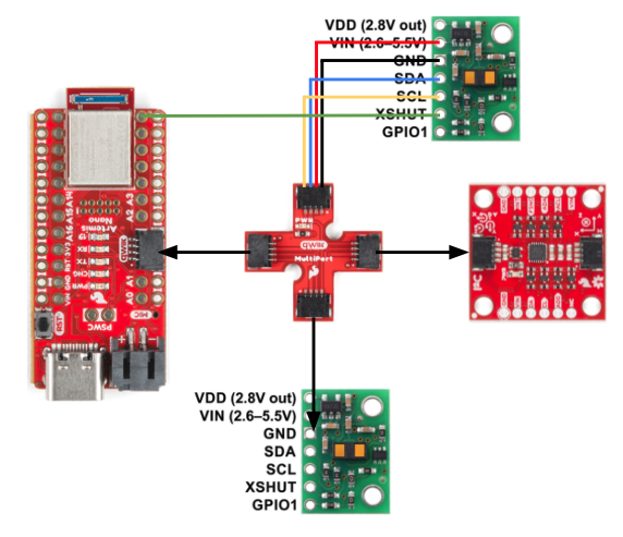
The datasheet shows that the I2C bus on the ToF sensor uses a device address of 0x52. Since we are using 2 of the same sensors with the same default address, I decided to use the XSHUT pin to change the address on one of the sensors. I chose this over changing the address programmatically for less wiring and power management. Using a jumper, I soldered the XSHUT pin on one of the sensors to the Artemis (pin A2) so that when powered on, the sensor connected can be held in shutdown mode while the address of the other sensor can be changed. This way, when the soldered sensor is turned back on, it can keeps its default address as the unsoldered sensor will have a new address assigned. Though there are some inconveniences to this method such as having to desolder if something goes wrong and needs to be initialized every startup, it is more suitable for this case where we want to minimize wiring.
Tasks 1 through 4: Hardware Things
In order to power my Artemis without having to connect to my computer, I soldered JST connecters to the 650mAh battery provided in lab.
I tested out the bluetooth connection using my code for Lab 2: IMU. IMU data was successfully transmitted via Bluetooth using the battery.
As of now, I plan to place one sensor in the front of the car and the other in the back. The sensors won't be able to detect obstables on the sides of the car due to their range, but I assume most of the motion would be backwards and forwards since the car cannot move directly sideways. I soldered the two longer QWIIC connectors to the ToF sensors so they can reach both the front and back, given the Artemis is placed in the center.
Below is a sketch of how I connected the wires.
Task 5: I2C Channel

Running the Example code for Wire I2C, I could see the address of the sensor printed to the serial monitor. While the datasheet showed that the default address for these sensors are 0x52, the printed address was 0x29. This is because the binary address was shifted one bit to the right, as 52 is 0b1010010 and 29 is 0b0101001 in binary.
Task 6: Short, Medium, and Long Distance Modes
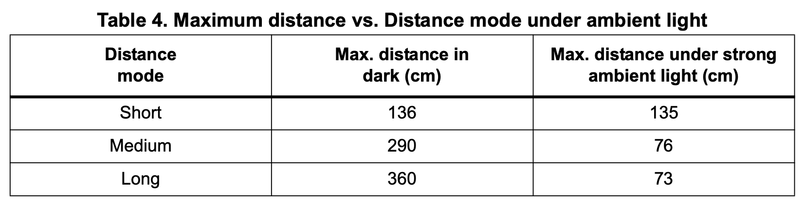
The ToF sensor has three distance modes: short, medium, and long, where medium distance mode isn't a built-in hardware feature but a mode that can be configured through software. The longer the distance, the more far out the sensor will be able to detect objects range the sensor covers but becomes more susceptible to ambient light. For this lab, I decided to use the short mode because I anticipate the car to go through abrupt changes in direction and flipping around obstables, rather than coasting for long distances. As long as the sensor can detect obstacles near the car, lower susceptibility to ambient light is better for my use case.
Task 7: Testing Short Mode
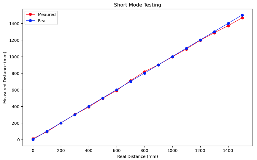
To test my chosen mode, I set up a tissue box at the end of a measuring tape and took 16 measurements in 100mm increments, ranging from 0 to 1500mm. I chose to test up to 1500mm because the datasheet lists the maximum ranging distance as 1300mm, and I wanted to see if accuracy noticeably decreases beyond that point.
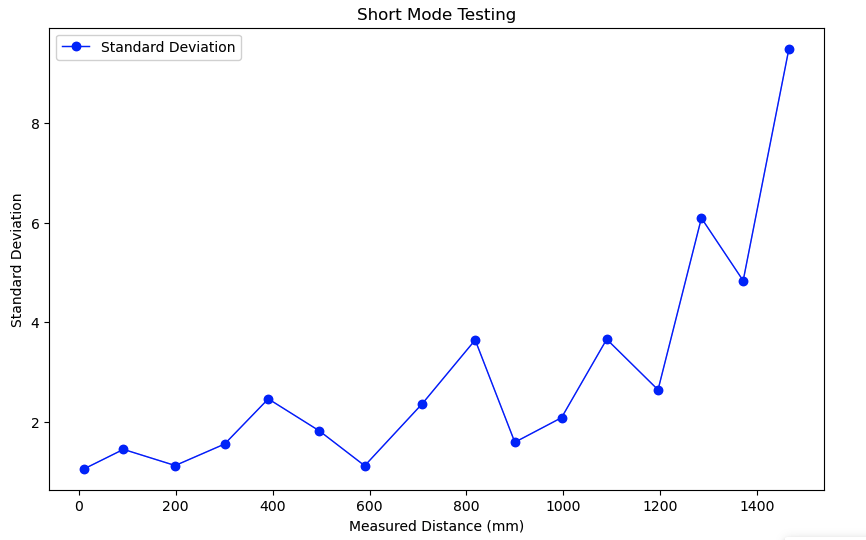
Below is the code I used for testing. I wrote a command that makes 50 measurements and takes the average and calculates standard deviation.
The first plot confirms the range specified in the datasheet, as it clearly shows that measurements beyond 1300mm deviate more from the actual value compared to those below 1300mm. The second plot indicates that measurements have a higher standard deviation for distances beyond 1300mm, indicating that as the distance increases, repeatability decreases. Timestamps also showed that there was about a 47ms delay between each date point.
Task 8: Connecting Both Sensors
Below is the code setup for collecting data from two ToF sensors simultaneously. As mentioned earlier, I used the XSHUT pin to enable both sensors, which share the same default I2C address.
At startup, the code turns off TOF1, the sensor with the XSHUT pin soldered to pin 8 on the Artemis.
The code then changes the address of TOF2 to NEW (which I set to 30), then turns TOF2 back on with its default address.
Below is the code in the main loop that constantly measures distance with both sensors, and a video of the code working.
Task 9: Cutting down execution time
In order to minimize execution time, I added code to record and print ToF data only when it is available.
From this, I could see that each ToF data point was printed approximately every 46,700 microseconds, while the loop executed every 5,200 microseconds, indicating that the ToF sensor's data collection speed is the limiting factor. This could be because the ToF sensor needs to wait for the emitted light to be reflected back before recording a measurement, causing a delay.
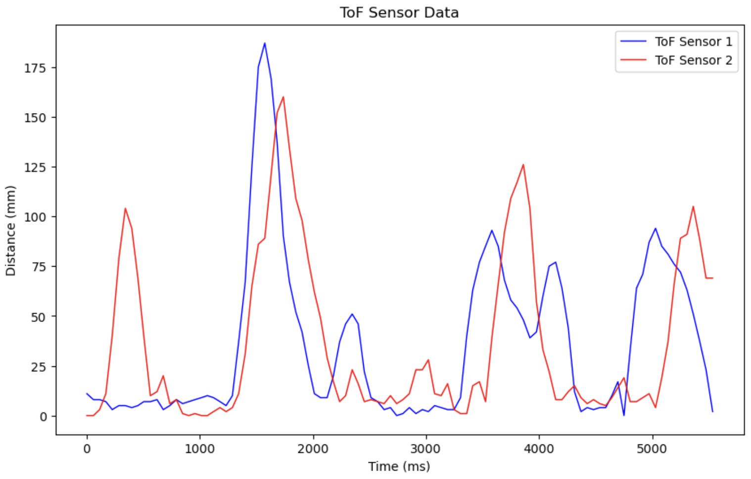
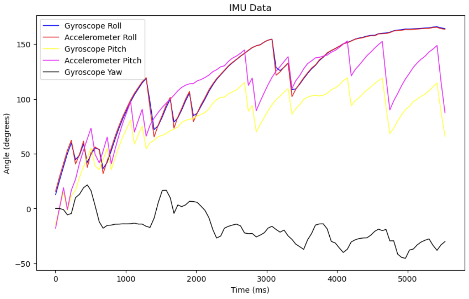
Tasks 10 through 12: Sending Time-stamped sensor Data over Bluetooth
Modifying code from labs 1 and 2, I was able to successfully measure and transmit data from the IMU and ToF sensors simultaneously, then plot it in Jupyter. Originally I was having a lot of trouble getting measurements from my ToF sensors, even though all my sensors were initiallizing correctly. I realized the issue was due to collecting too much data with 7 arrays with a size of 2000 for all three sensors, possibly resulting in communication bottleneck especially since the IMU collects data much faster than ToF sensors can.
I included the actual code in the appendix below, as it is quite long and I did not make any significant changes to the code from Lab 2 and previous tasks.
Discussion
This was my first time learning how to solder properly.
References and Acknowledgements
- This forum on XSHUT pins
- Jeffery Cai for catching my silly mistakes
- Nidhi Sonwalker's website
- Stephan Wagner's website
Appendix
- Below is the code for sending both ToF and IMU data over bluetooth.